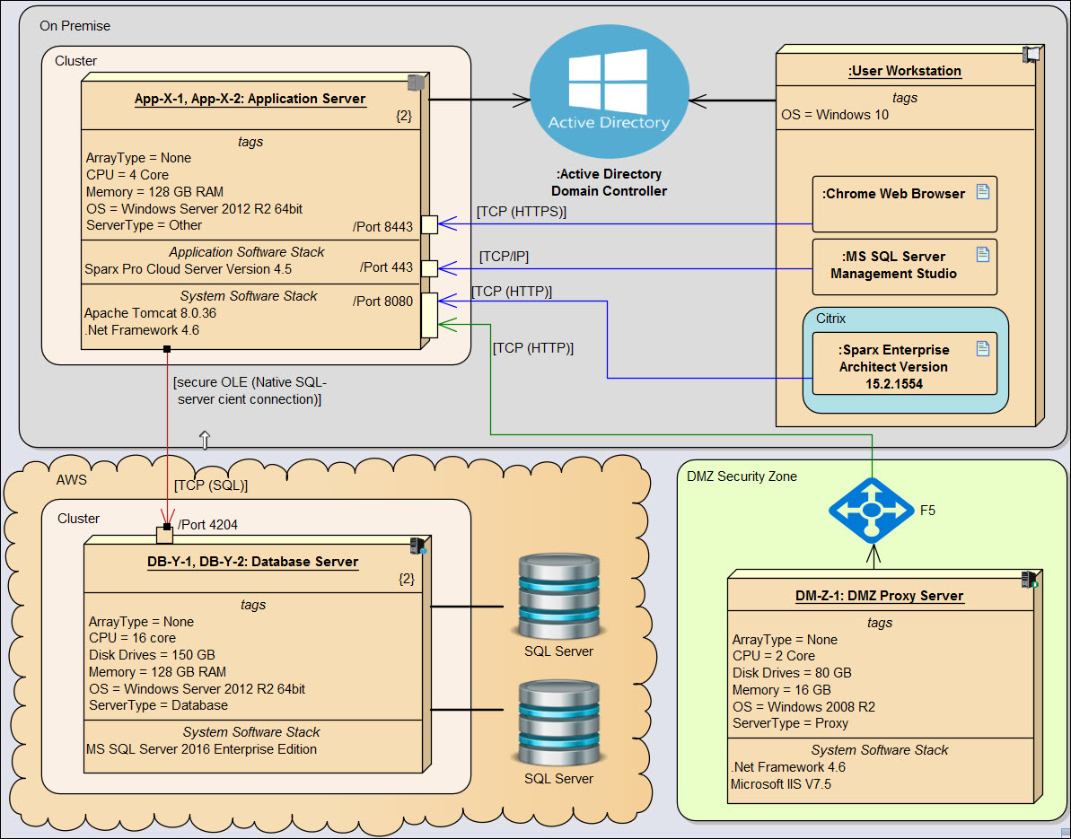
 This add-in to Enterprise Architect (version 16.x or later) embeds a UML® profile (inside an MDG Technology) to facilitate the modeling of complex system architectures using UML Deployment diagrams. Often these types of diagrams are built in Microsoft Visio to take advantage of its graphical representation features.
The profile allows the Enterprise Architect modeler to quickly build visually appealing system architecture diagrams that convey a maximum of technical information in a minimum of graphical footprint.
The main features of the extension are:
- A new System Architecture diagram. Its toolbox/stencil includes:
- Standard UML Deployment diagram types such as Node, Device, Artifact, Communication Path, Deployment, and Manifest.
- Software artifact types: Application, System, Other, and Gateway, each with predefined custom properties such as date-in-production, date-retired, release & version number, vendor name, and status.
- Specialized deployment node types for modeling:
- Servers (application, database, directory, mail, printer, and web), each with predefined custom properties including hardware, IP address, physical location, OS, and array type (pooled, clustered, etc.).
- Network Ports.
- Other node types: Bastion Host, Laptop, Mobile, Website, and Workstation.
- Devices: Database, Load Balancer, and Router. Each of these support relevant properties.
- Network types: Firewall, Network Protocol, Network Element, and LAN, with custom properties where applicable.
- Deployment environments: Cloud, Context, Internet/Intranet, Network Zone, and SaaS Provider.
- A Network Link connector, with custom properties to identify its Network Protocol (HTTP, HTTPS, SOAP, SSL, etc.), content type (e.g. XML), and target port number.
- Most elements specializing either UML Node or Device can be graphically represented in one of 3 ways:
- Image only. The toggle can be set at the element level, or for the entire diagram.
- Standard UML rectangle, but with a small image in the right hand corner, with or without custom properties (tags) visible.
- Same as above, but with distinct compartments visible to document the software artifacts (application, system, or other) deployed on a node (when these artifacts are not graphically displayed on the current diagram).
- Image only. The toggle can be set at the element level, or for the entire diagram.
- Also included is a library of predefined elements, provided as a starting point for the modeler. The diagram shown above is built up from the constructs in the library, which includes examples of:
- Application, System, and other software artifacts.
- Servers, Databases, and deployment environments.
- Network Protocols.
Additional custom properties can of course be added to any System Architecture element.
For further details of how the extension operates, please see the End User Documentation.
To customize this extension in order to meet your specific system architecture modeling requirements, please contact us!
Related Extensions
Pricing
Quantity Fixed license 1-4 USD 50.00 5-19 USD 35.00 20+ USD 25.00
Download the trial version to test out the extension, or place your order now.
Trial Request
Simply fill out the form below and we will email you the password providing access to the download page of the trial version. Also make sure that the End User License Agreement is in accord with your company's legal standards!
Please view our Privacy Policy page if you have concerns about filling out this form!
